(800) 343-1391 • (603) 749-6434
www.aemc.com


Legal Challenges to US import tariffs — Update
ⓘ Due to recent tariff adjustments, product prices may be affected, and some surcharges may not yet be included in the prices shown.
We’re Sharing the Burden — Absorbing 50% of Tariff Costs to Help You Save. Learn More.
ⓘ Debido a los recientes ajustes en aranceles, los precios de los productos pueden verse afectados y algunos recargos podrán no estar incluidos en los precios mostrados en nuestro sitio web.
Para ayudarle a ahorrar, estamos asumiendo el 50% del costo de los aranceles. Más información en este enlace.
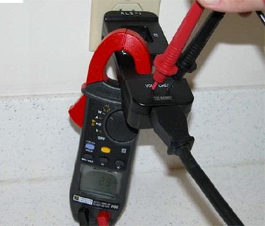
How to Measure Power with a Clamp-on Meter
THEORY OF OPERATION
A magnetic field, proportional to the magnitude of current, surrounds all current carrying conductors. In an AC circuit the magnetic field will induce a current in the jaws of a clamp-on current probe when the jaws are closed around the conductor. If both conductors of the circuit are enclosed by the jaws of the probe the magnetic fields will cancel and no measurement is possible. Most 120 V AC appliances use two conductor cords which make it difficult to isolate a single conductor for measurement. The ALS-1 provides temporary separation of conductors to facilitate measurement of current.
OPERATION
- Plug the ASL-1 into a grounded type 120V AC receptacle. If a grounding type receptacle is not available, a 2 to 3 wire adapter must be used. Maintain ground wire integrity to minimize the possibility of electrical shock.
- Plug the appliance line cord into the end of the ALS-1 and turn on the appliance.
- Place the jaws of the clamp-on current probe through the X1 section of the ALS-1. The current being drawn by the appliance can then be read directly from the indicator of the clamp-on probe.
- If the magnitude of the reading obtained in step 3 is less than one-tenth of the full scale range of the clamp-on current probe, and difficult to read, place the jaws of the probe through the X10 section. The magnitude of the current drawn by the appliance will be the reading on the current probe meter divided by ten.
Example: With the range switch of the clamp-on current probe set to 6 AMPS, the meter indicates 5.4 amps, and the jaws of the probe are through the X10 section of the ALS-1. The actual current is 0.54 amps (5.4 amps ÷ 10 = 0.54 amps, or 540 mA).