(800) 343-1391 • (603) 749-6434
www.aemc.com
- Mega Menu
- Products
By Industry
Other Product Lines
- Learn
- Resources
- Support
- Customer Service
- Export
- Join our Mailing List
- Legal Notices
- Literature Request
- Policies
- Product End-of-Life Policy
- Private Training
- Repair and Calibration Services
- Returns
- Safety and Recall Notices
- Sales Support
- Software/Firmware
- Technical Support
- Terms and Conditions
- Training Seminars
- Training Webinars
- Warranty Registration
- Where To Buy
- Store
- About Us
- Contact Us
- Products
- Cable Testers
- Clamp-On Meters
- Current Probes
- Data Loggers
- Decade Boxes
- Power Supplies/Generators
- Digital Multimeters
- Electrical Test Tools
- Environmental Testers
- Ground Resistance Testers
- GroundFlex® Field Kit
- Static Ground and Bond Test System Kit
- High Voltage Testers
- Megohmmeters - Insulation Testers
- Micro-Ohmmeters
- Multi-Function Installation Testers
- Oscilloscopes
- Power Analyzers / Energy Loggers
- Tachometers
- Thermal Imaging
- Digital Transformer Turns Ratiometers
- Accessories
- Learn
- Articles
- Resources
- Support
- Where to Buy
- Store
- Company
- Contact Us
ⓘ Due to recent tariff adjustments, product prices may be affected, and some surcharges may not yet be included in the prices shown.
We’re Sharing the Burden — Absorbing 50% of Tariff Costs to Help You Save. Learn More.
ⓘ Debido a los recientes ajustes en aranceles, los precios de los productos pueden verse afectados y algunos recargos podrán no estar incluidos en los precios mostrados en nuestro sitio web.
Para ayudarle a ahorrar, estamos asumiendo el 50% del costo de los aranceles. Más información en este enlace.
Current Probes

Why Choose AEMC® Instruments Current Probes?
The Most Comprehensive Line of Current Probes
AEMC® Instruments the world's largest supplier, offers current probe models capable of accurately measuring from the low µA to kA range. A wide variety of configurations and jaw sizes are available.
Probe types include iron core, Hall Effect, Flux Gate, and Rogowski.
Highest Quality
Our range of current probes are compact, simple-to-use, accurate and are designed and tested by electrical engineers offering superior knowledge in safety and time-saving features to help you confidently troubleshoot and solve problems.
Safety
Our current probes are designed, manufactured and tested to meet the latest safety and measurement standards (IEC EN 61010/ EN 61010-1/NF EN 61010-2-30, (300, 600, and 1000) V, CAT III and CAT IV).
Easy Interface Options
Standard and customized output options provide easy interface to data loggers, meters, oscilloscopes, control systems, and more.
Custom Probes
AEMC® offers custom probes to meet your application. Just let us know your specific needs.
Tech Support
AEMC® provides complete technical support through our technical hot line 800-945-2362 (ext.351), speak directly to one of our tech support staff today. Or e-mail your questions to our tech team. techsupport@aemc.com
Current Measurement Probe Comparisons
We created this all-in-one comparison document to help you select a proper Clamp-on Current Probe for your specific needs.
Current Probes
-

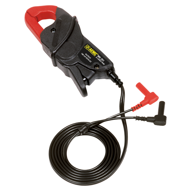
AC Current Probe Model MN291 (refurbished)
Cat. #2115.84
200A, 100mVDC per AAC, Lead
Designed for digital multimeters, loggers, and other instruments with DC voltage inputs. Enables measurement or recording of current with instruments without current ranges. VDC output (100mVDC per AAC) is proportional to the current measured (through the jaws). Features integral 5’ (1.5m) leads terminated by shrouded banana plugs. -

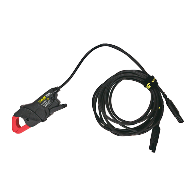
AC Current Probe Model MN82
Cat. #2135.71
For Models 6471 & 6472
Designed specifically for use with the AEMC Ground Resistance Tester Models 6471 and 6472. When one probe is used in the traditional Fall-of-Potential method, selective grounds can be measured by moving the probe from point to point around the grounding system. When two probes are used with the Model 6471 and 6472, grounding electrodes can be measured without needing to install auxiliary rods and conducting a Fall-of-Potential measurement. (This is called the “stakeless” method.) -

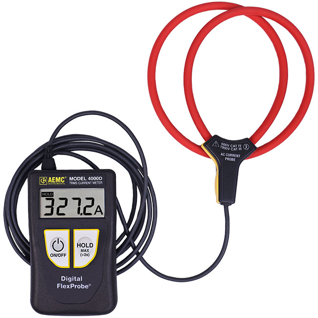
Digital FlexProbe® (MiniFlex) (refurbished)
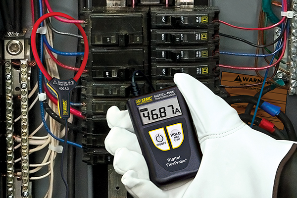
An ideal addition to the electrician’s tool kit, the Digital FlexProbe® series can be used for TRMS AC current measurements and are rated at 600 V CAT IV. They provide a welcome solution when accessing electrical conductors in difficult and tight places.


